top of page
Hybrid Matrix Ribbon Rig
After learning how to use matrix math to create the robot rigs for our game "Rage Quit", I was inspired to learn more once I had the time to do so. Our robot characters were designed so the robotic arms and legs were hard surface objects that didn't need extra rigging required to create bends, arcs, and twists. After finishing the game, I wanted to come back to the idea of creating traditional style ribbon rigs using matrix math. My resulting ribbon has NO constraints, blend shapes, clusters, or skin weights. I haven't seen any other ribbons created exactly like this online, and in this article I will explain my thought process, how I made it, how my ribbon compares to older styles of ribbons, and my next steps moving forward.
In this process, also I wanted to learn exactly why the newer process was faster. I took a deep dive into understanding serialization, parallelism, how nodes are evaluated, how to read visual evaluation graphs, and how to identify issues in my rig. In this article I go into full detail by comparing the metrics and structure of an older, legacy based traditional ribbon vs my newer, math based approach to a ribbon.

Goals
Ribbon rigs are incredibly useful for animation, however they are extremely costly and performance heavy. I wanted to create a ribbon rig that minimized performance impact while maintaining animation capabilities.
What I wanted in my rig:
1) Infinite/ non-flipping twist
2) Bend controls
3) Extra bend controls
4) Parallel evaluation friendly
What I wanted to avoid in my rig:
1) Constraints
2) Blend shapes
3) Skin weights
4) Clusters
5) Deformers
I want to avoid these types of tools because of how they are evaluated by Maya. These types of nodes are not parallel friendly and they will dramatically slow performance.
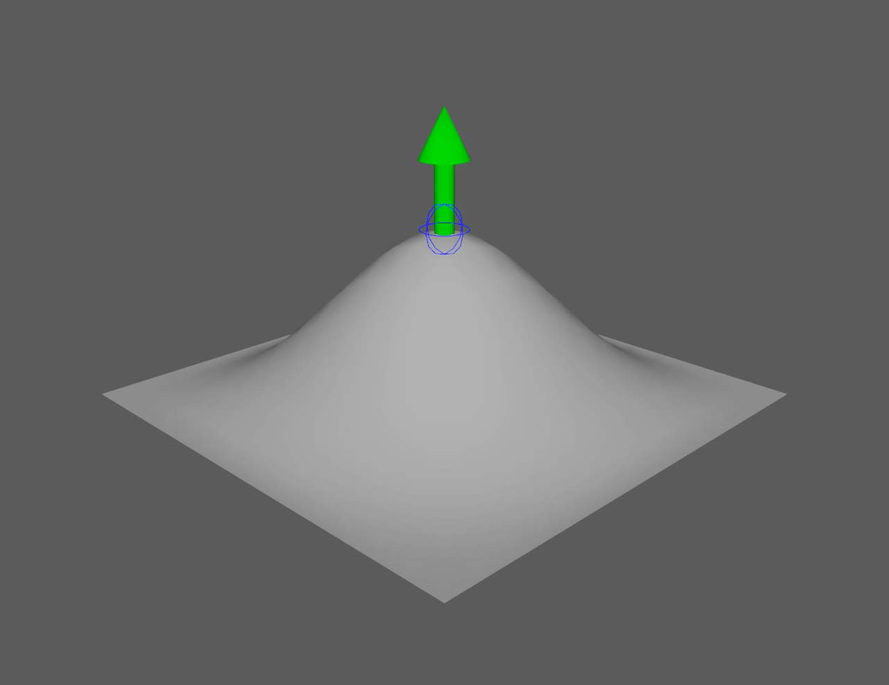
This is the resulting ribbon animated with skinned geometry:

Read about how my ribbon was created to animate this range of motion
Animation by myself
Parallel Evaluation
Before we begin, we need to understand the difference between parallel & serial DG (Dependency Graph) evaluation.
Parallel evaluation is the ability of a system to process multiple operations at the same time, spreading the workload across multiple CPU cores. The alternative to this is a process in which each operation is processed in a strictly sequential order. In Maya's case, this is DG evaluation.
Think of this scenario: You have a room with 10 boxes, and you need all of the boxes opened.
DG Evaluation (Serialized) = Telling 1 person to go into the room and open the boxes. The processing time is going to be slow because this 1 person has to open the boxes one-by-one, they can't open 10 at the same time.
Parallel Evaluation (Non-Serialized) = Telling 10 people to go into the room, each grab a box, and open it. The processing time is going to be much faster because each box is opened simultaneously. This is a non-serialized workflow.
Old Maya started with serialized DG evaluation, which means that nodes were evaluated sequentially, even if they were independent from each other. DG evaluation was a great practice when hardware & software were older and more limited in power. It also helped with ensuring correct results from an operation since everything was streamlined into a singular, hard hitting chain of events. As a result of this, nodes were created to fit a DG friendly sequential order of events.
Nodes fitting a DG workflow are dependency based. They're designed to fit into a sequence, meaning that they require a specific order. Nodes in the chain are completely dependent on the prior sequence of events (sequential dependency) or stored information (stateful).
Around 2016, newer versions of Maya began to use parallel evaluation. This meant that Maya could now process multiple operations across multiple CPU cores. The issue though is that Maya can't simply evaluate everything separately, as older nodes were not designed with parallel in mind. This means that some nodes force serialization (one-by-one), even in a system that could do more, which creates slow bottlenecks and underutilizes modern hardware. To counter this, newer parallel friendly nodes were introduced.
Nodes fitting a parallel workflow are independent. They aren't forced into a chain and they don't rely entirely on the prior sequence (independent) or stored information (stateless).
Think of this scenario: You want someone to open a box and take the contents out.
Dependency Node (Stateful) = This box would be a huge, heavy box with layers of duct tape, plastic, and styrofoam. This box also requires an instruction manual and a tool to open. Inside the box are a lot of contents. Opening this box relies on the person getting the instructions and tool first. The person then has to do a lot of work following the instructions to open the box and bring the contents out. They're relying on the instructions to open the box the entire time.
Independent Node (Stateless) = This box is a tiny, light box that has an easy lid to open. No instructions or tools are needed. Inside the box is nothing but a small amount of contents. The same person has no issue effortlessly opening the box and taking the contents out right away.
Older serialized DG style nodes create huge bottlenecks because they are trying to process too much information and especially prior results earlier in the chain. They can't be evaluated in parallel because of this. Instead, parallel evaluation favors smaller nodes that are processing only a small amount of information independently.
What does this mean for my rig?
If I want a faster performing rig I'll want to use parallel friendly nodes like matrix math nodes and avoid using larger dependency based nodes like deformers.
Important Note: All nodes live in the DG (Dependency Graph), parallel evaluation is just a newer mode of evaluation. Parallelism isn't just a result of how a node is created, but also how it is connected. Think back to the boxes. The parallel nodes are easier to open and multiple can be opened at the same time.
Getting Started
Like my robot rigs, I once again had to "start over" from the beginning. This meant I had to look back on older ribbon rigs and learn how they worked under the hood.
The first issue I tackled was the problem of getting a joint to follow the surface of a NURBS plane.
Traditional ribbon rigs use nHair follicles to get a UV point on a NURBS surface and joints are then parented to these follicle nodes. The surface itself is then usually driven by a deformer of some kind. With this setup, the order basically goes:
Controller → Deformer → NURBSRibbonShape → nHair Follicle → Joint.
While this method works for getting desired animated behavior, it is performance heavy due to the deformer and hair follicle. Deformers like clusters, blendshapes, and wires are heavier to process and are not parallel-friendly due to creating a serialized chain. A deformer evaluates the entire ribbon as a whole, making it slower to process because everything must go through that deformer bottleneck.
Hair follicles are also very heavy. The nHair follicle system is built for simulation, and even when you aren't using them, the support structure for attributes like dynamics, constraints, simulation states, and hair settings are still being processed. This creates another bottleneck that isn't parallel friendly, which makes sense because the nHair system was introduced before modern parallel evaluation in Maya.
With newer Maya math nodes, we can get around these 2 issues while maintaining the same desired animated behavior. To do this, I use a uvPin node to follow a point on the NURBS surface and to drive the joint. To drive the surface, I used a pointMatrixMult node. In my example, my new order goes like this:
Controller → pointMatrixMult → NURBSRibbonShape → uvPin → Joint.
The deformer is replaced by a significantly lighter pointMatrixMult node. This node takes a matrix value (in this case the world matrix of the CTRL) and passes this position into a control point in the NURBS ribbon. This node is just passing math and it is only evaluating a single control point on the ribbon, rather than evaluating the entire ribbon. This node is also not trying to read into anything prior to the controller. Due to its small and independent structure, it is parallel evaluation friendly because multiple of these tiny nodes can be processed at the same time.
Next, the uvPin node is where the bigger performance impact is seen. A uvPin node is much smaller than a follicle node, as it isn't processing an entire simulation system. Instead, it is just getting the position from a NURBS surface and following that point. This node isn't entirely independent though as it is reading the information of a deformed geometry. It is still parallel friendly though because one uvPin isn't reliant on the results of another uvPin, rather they can all be processed at the same time still.
In the below images, I compare the node network of the old setup vs my new setup. From a visual perspective, you can see the difference in node sizes. On the left, you can see the much larger deformer (blend shape) nodes, hair follicles, and parent constraints. On the right, you can see the tiny matrix math nodes being used to pass math.

Old joint structure

New joint structure
The examples above are an isolated example for a single joint. In a ribbon rig, this network is scaled up to include 5 joints. On the left, the sequence chain grows longer, creating an extended bottleneck. On the right, it can be seen how multiple pointMatrixMult nodes are being processed at the same time. The hair follicle & uvPin nodes look like they're both being evaluated separately though. Under the hood, the hair follicles are lining up in order, Maya can't process them all at the same time. All of the uvPin nodes can be evaluated simultaneously under the hood. What is seen on the right is more accurate to how the rig is being evaluated.

Old ribbon structure

New ribbon structure
Why is this important?
The difference between these rigs can be seen at a smaller scale, but it is really felt in a much larger scale. A typical character will have multiple ribbons. For example, an arm has 2 ribbons, 1 for the upper arm and 1 for the forearm. This is where scalability matters. In the example to the left, imagine extending that chain out 8 times in a long horizontal chain. In the example to the right, imagine this structure stacking up vertically, all having a similar starting point.
Maya can process the large stack of smaller nodes much faster than the long chain of bigger nodes.
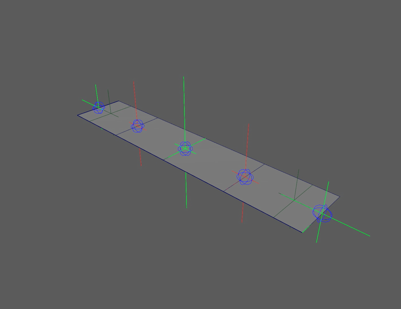
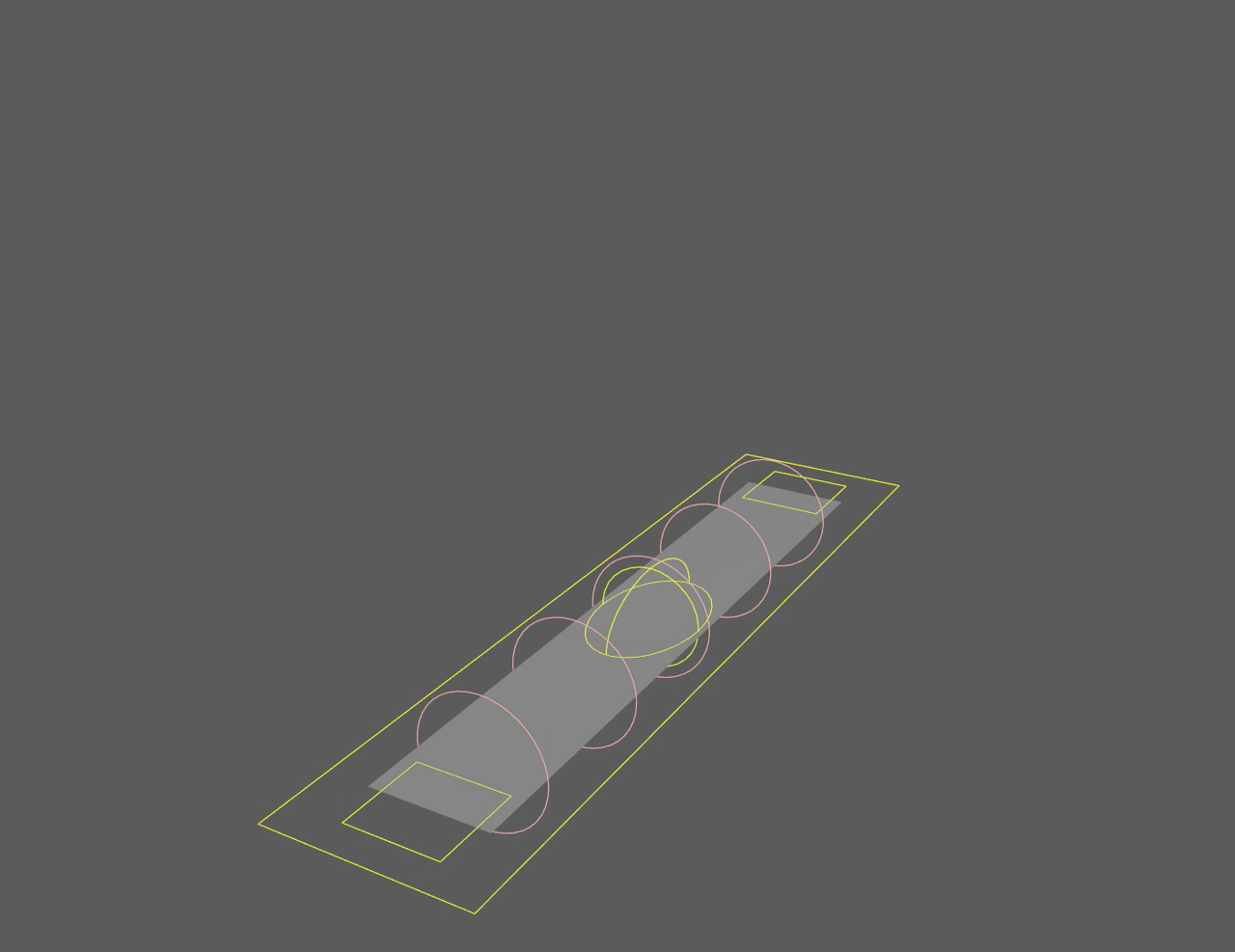
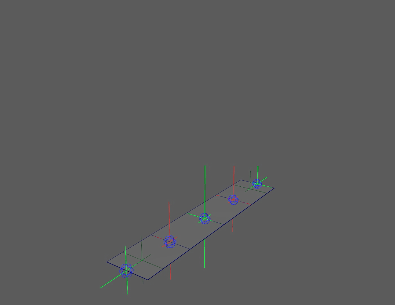
Ribbon Structure
Now that we've covered the different nodes and why they matter, let's look at how the ribbon rig behavior is built. For my ribbon, I want it to be able to twist infinitely, bend, and physically scale in the middle or ends.

Old ribbon

New ribbon
Both of these ribbons give me the same behavior, however it can be easily seen how they differ. On the left exists a larger outliner cluttered with bottleneck nodes & tools. The extra blend shape ribbon can also be seen past the main ribbon. On the right is a much cleaner outliner with no constraints, deformers, blendshapes, or clusters. All of the math for the behaviors is set up in the node editor. (Refer to the ribbon structure images)
The left side ribbon gets animation behavior based off of the blendshape ribbon. The blendshape ribbon is being deformed by a twist deformer and a wire deformer, this gives it twist and bend. This is already a large process as each deformer works in a sequence, and then that piece of geometry is then read by the main ribbon. That's 2 entire ribbons being evaluated already, and one depends on the other, and that other one depends on the deformers. Once the behavior is created, joints (hidden under the hair follicles) then follow the hair follicles. The hair follicles are reading the geometry, carrying the simulation system, working one at a time, and finally driving the joint.
The right side ribbon gets animation behavior because of how I set up the math in the node editor. Instead of deforming geometry, I get the animation behavior by feeding translation data through math nodes from one controller to the other.

Twisted and bent by a blendshape with deformers

Twisted and bent directly from the controllers to the ribbon

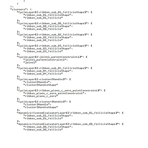
The node process for getting twist, bend, and scale on the new ribbon
In this screenshot, I breakdown how I get my animation behavior.
1) A plusMinusAverage node is used to get twist by taking the rotation values of the end controllers and outputting the average between them. For example, if loc_05 rotates by 50°, loc_03 is rotate 25°.
2) An aimMatrix node is used to keep the middle locator pointing towards direction of the end controllers which matters for both twist and bend. This is done by plugging loc_01's world matrix into the input matrix, giving it a starting point to aim. This makes the locator aim at loc_01, but only from a stationary point. If the other end of the ribbon is moved and the middle controller is moved up in space, it is now pointing at an area above loc_01. To fix this, loc_05's world matrix is plugged into the primary target matrix. This way loc_03 also identifies loc_05 as a point to aim at, and by also pointing at loc_05, it will point the other end towards loc_01. The loc_03 now has 2 points it is aiming at. The secondary target can then be used for a Y-up aim, but in my example I don't have that. These values are then taken and plugged into the Y & Z axis of loc_03.
The reason this issue needs to be solved is because wherever the middle points dictates how the ribbon will deform. Remember, the locator is directly driving the geometry, therefore it needs to follow the direction of the end locators. I don't want the twist to bend at an incorrect offset, I want it to bend facing the direction of the ribbon.


3) A blendMatrix node is used to drive the position and scale of the middle locator. This node is set up to be the average between loc_01 and loc_05. It is setup in the offset parent matrix so that the translation and scale values of loc_03 can be used to create a bend. The blendMatrix node is run through a pickMatrix node where I cancelled out the rotation. I wanted to use this node for translation and scale, not rotation.

This same setup can then be replicated for the other controllers between the middle and ends to give an extra layer of control. The red controllers (loc_02 & loc_04) now follow twist, aim, bend, and scale behaviors as well.


All controllers connected to twist, bend, and scale the entire ribbon
One aspect to note is that I am using the plusMinusAverage to get rotation and not the blendMatrix. This is intentional, as those 2 nodes work differently in how they read the inputs.
The blendMatrix is reading an input entirely with orientation, position, scale, and shear. To process this input, the node uses quaternion interpolation behavior to give the most stable result. This means that it is taking the shortest possible path to reach the desired state. This works perfectly for position, however the issue presents itself with rotation. When quaternion interpolation is used, it is essentially saying "what is the shortest path within a 360° orientation".
The plusMinusAverage node isn't reading the rotation X values as rotations or trying to interpolate orientation. It simply sees a float value, it doesn't read the input as an object orientation. This means that it'll never try to take the shortest path.
For example, say you want a controller rotated 270°:
Quaternions: 90° → 180° → -180° → -90°
In this case, -90° is a shorter path from 0° than 270°, therefore it "flips" when it hits 180° because anything past that would no longer be the shortest path.
Non-quaternions: 90° → 180° → 270°
In this case, there is no "shortest path", it is just a number that scales up.
This "flip" in the controllers can be seen in the left side ribbon below. It
severely limits animation. The right side ribbon can twist infinitely and
never flip, giving animators more freedom to push rigs.
Quaternions (red) flip at 180°, floats (green) never flip

Ribbon twist with flipping
Ribbon twist without flipping
Evaluation Performance
Now that we've looked into how my rig differs from the old one, let's take a look into the metrics that show the difference in speed and evaluation. Below I have both old (left) and new (right) ribbons being tested with the same 24 frame animation of a 360° degree twist, 1 end being raised, and the middle bend controller creating a bend.
Old ribbon
New ribbon
With our test animation set, we can now look at 4 different visuals to see the performance difference.
1) Profiler: Visually shows the total measured time per frame to evaluate all nodes and the ribbon overall. Also shows the node costs and data categories of each node.
2) Visual Graph: Shows the dependency relationships between nodes, not animated runtime.
3) Visual Scheduling Graph: Visually shows Maya's planned node execution for animated runtime.
4) Text Scheduling Graph: Textually shows more detail in Maya's planned node execution for animated runtime.
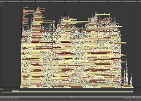
1) Profiler
The profiler is what I will use to record the animation and look at how Maya evaluates the ribbon per frame. It will show how long it took, any nodes that create bottlenecks, how parallel the rig is, and the information of how each node was evaluated. Time is measured in microseconds (μs) and milliseconds (ms).

Old ribbon animation profile

New ribbon animation profile
In the examples, we are looking at how the ribbon was evaluated in 1 frame of animation. The highlighted "Main" bar (EvaluationGraphExecution) is where the total time evaluated is shown, the average time per frame for each is:
Old Ribbon: ≈ 1400 μs (1.4 ms)
New Ribbon: ≈ 1200 μs (1.2 ms)
On the old rig we can identify the 3 bottlenecks forcing serialization, and upon going to these sections, we can see they are the wire, blendshape, and nurbs ribbon shape nodes. In the new rig we only see 1 bottleneck, that being the nurbs ribbon shape. From this information we can see that both of these setups have joints that rely on the nurbs shape to be evaluated first, but the deformation is distributed upon more parallel friendly math nodes than serialized deformers.
Seeing the difference on the small scale, we can already predict that in a large scale test that the new ribbon will be faster. This is because it has more parallel friendly nodes that will scale better than serialized nodes adding up.
To see how these rigs compare, I took the same ribbon animation and replicated it 100 times in the same scene.
Old ribbon animation 100x profile

New ribbon 100x animation profile
Once again we are looking at a single frame of animation, and in the EvaluationGraphExecution we can see a more distinct difference in time.
Old Ribbon: ≈ 8300 μs (8.3 ms)
New Ribbon: ≈ 6700 μs (6.7 ms)
This proves that the use of math nodes instead of deformers is spreading the workload more and getting a faster result of it. This is around a 20% increase in speed from the older rig.
2) Visual Graph
Going back to the singular ribbon, the visual graph isn't going to display measured time. Instead, all it will show is the dependency relationships in the construction of the ribbon. Here, it is more clear to see what relies on what, and which nodes can be evaluated in a serialized vs parallel order.

Old ribbon visual graph

New ribbon visual graph
On the left, it can be seen that the much heavier nodes must follow a distinct order. The twist, wire, and blendshape deformers follow a chain of operation to the nurbs ribbon shape, math is not spread out. On the right, it can be seen that the deformer math is spread significantly more evenly. This confirms that the new ribbon is parallel friendly! The bottleneck of the nurbs ribbon shape can also be identified with this visual, confirming what we saw in the profiler.
This graph also provides useful information by outlining what is being cycled and what is being pruned.
Cycling is bad to see as it means a node or node network is depending on itself. This causes an infinite loop, therefore Maya has to resolve/ break the cycle by forcing serialization. Many legacy nodes are built with intentional cycles, causing more work needed for evaluation.
Pruning is good to see as it means parts of that node aren't needed downstream and can therefore be disregarded in evaluation. This simply means whatever is being pruned gets cut and less work is needed to evaluate that node.
In the older ribbon there are cases of both cycling and pruning. In the newer ribbon, there is no cycling at all, only pruning.
3) Visual Scheduling Graph
Returning to the animated ribbon, the visual scheduling graph is displaying how Maya anticipates the nodes to be executed in runtime.

Old ribbon visual scheduling graph

New ribbon visual scheduling graph
Like the original visual graph, the same patterns can be seen here. On the left is a more serialized order of events, and on the right the math is distributed to be parallel friendly. Once again this graph can show cycling and pruning within the nodes, this time in the expected order of execution.
4) Text Scheduling Graph
This is simply a text output of the scheduling graph, the same information from the visual graph will be seen here. These text outputs also show the cycling, pruning, and caching in the scheduling. The below pictures are only snippets of the full text output, but the difference between serialization and parallelism can still be seen.

Old ribbon order of execution, note how there is a "stair steps" order in how nodes are evaluated (one at a time)
Old ribbon shows cycles and dynamics

New ribbon order of execution, note how large blocks of multiple nodes are evaluated at the same time

New ribbon shows pruning and caching
The text output of the visual scheduling graph makes it easier to search through nodes and see evaluation in more detail. One aspect that is easier to see in this output is the caching of nodes. Caching is good to see as it means information is being stored and doesn't need to be re-evaluated later.
The Result
My resulting ribbon successfully proves that my approach is faster! I learned how to completely avoid using deformers all while keeping the same range of motion as a traditional ribbon. I also learned how to measure many aspects of my rig and how to compare it to older ribbons.
I successfully completed my goal of recreating a traditional ribbon, however I was still left wondering "could I make this faster?". The resulting rig is fast, but it's not as fast as I want it to be.
There was a glaring bottleneck in my new ribbon, that being the NURBS ribbon shape itself. It is important to have this geometry to achieve the smooth motion that ribbons are known for, but the ribbon was killing performance. Looking into it, I understood that the ribbon was only there to drive the position of the joints.
"Could I make a ribbon rig without the actual ribbon?"
The answer is yes. After re-evaluating the rig and seeing the ribbon as a legacy approach, I decided to completely cut out the ribbon and do the math entirely myself. My new resulting ribbon is now over 3x faster than the original ribbon, and over 2.5x faster than the hybrid ribbon! There are no bottlenecks in evaluation and everything is parallel friendly.
To read about my new ribbon, follow the section below.

Pure Math Ribbon Rig
Learn how I improved upon my hybrid matrix ribbon rig and made it over 2x faster with no NURBS and only using math nodes to make it parallel friendly.
bottom of page