top of page
Pure Math Ribbon Rig
My hybrid ribbon was a result of combining newer methods with traditional methods, that being matrix nodes to drive a NURBS plane to get a ribbon rig. This was very useful for learning more about matrices and how to examine performance in rigs, but my resulting ribbon still wasn't as fast as I wanted it to be. Using the profiler, I was able to locate the exact bottleneck in my ribbon, which was the NURBS plane. This geometry was forcing serialization because in order for the rig to be processed, the entire geometry needed to be evaluated so that the joints could move. I wanted to cut this out entirely, which lead me to the question:
"Could I make a ribbon rig without the actual ribbon?"
The answer is yes, I was able to recreate a ribbon rig to share the exact same range of motion (and a few more) solely using math nodes. In this article, I will take you through my thought process, how I made it, challenges, and how it compares to my hybrid rig.

Goals
My main objective was to eliminate the NURBS plane of the ribbon rig without losing any of the animation abilities. I wanted to make the rig purely using math without any deforming geometry, curves, or external plugins.
What I wanted in my rig:
1) Infinite/ non-flipping twist
2) Bend controls
3) Extra bend controls
4) Parallel evaluation friendly
5) Vanilla Maya nodes
What I wanted to avoid in my rig:
1) Geometry/ curves
2) Plugins
The reason I wanted to avoid plugins for my first attempt is so I could learn the issues and limitations myself.
This is the resulting ribbon animated with geometry skinned after rigging:

Read about how my ribbon was created to animate this range of motion, the same exact keyframes as my hybrid rig
Animation by myself
Getting Started
Recreating the ribbon rig for a second time, I didn't have to "start over" like I did with my hybrid ribbon. I already had the basis for creating the animation behavior which would save me a lot of time. The challenge came from learning how to recreate the NURBS geometry "smoothness" of flowing curves and faces. To do this, I had to look back at my hybrid rig and map exactly what the controllers were doing vs what the geometry was doing. The controllers were already giving me twist and proper aim, but the positioning and Y-up/ normal direction was provided by the geometry. These would be the point of focus for building my new rig.
I wanted to note though that the NURBS geometry method from before isn't useless to know. For scenarios where I need an object to follow along an animated/ deforming surface, I now have a solution ready to go with matrix nodes.
Note how when translated, one section of the geometry will partially drag the surrounding areas with it, giving it a smoother appearance. Joints also follow the normals, meaning they rotate to follow the curve of the geometry.
Objects can easily be driven to follow the UVs of any given geometry
Parallel Evaluation
Keeping with the theme of a parallel friendly rig, I wanted to make this rig as optimized as possible for evaluation. If you read my hybrid ribbon article, you can skip this section as it is just a refresher.
Parallel evaluation is the ability of a system to process multiple operations at the same time, spreading the workload across multiple CPU cores. The alternative to this is a process in which each operation is processed in a strictly sequential order. In Maya's case, this is DG evaluation.
Think of this scenario: You have a room with 10 boxes, and you need all of the boxes opened.
DG Evaluation (Serialized) = Telling 1 person to go into the room and open the boxes. The processing time is going to be slow because this 1 person has to open the boxes one-by-one, they can't open 10 at the same time.
Parallel Evaluation (Non-Serialized) = Telling 10 people to go into the room, each grab a box, and open it. The processing time is going to be much faster because each box is opened simultaneously. This is a non-serialized workflow.
Old Maya started with serialized DG evaluation, which means that nodes were evaluated sequentially, even if they were independent from each other. DG evaluation was a great practice when hardware & software were older and more limited in power. It also helped with ensuring correct results from an operation since everything was streamlined into a singular, hard hitting chain of events. As a result of this, nodes were created to fit a DG friendly sequential order of events.
Nodes fitting a DG workflow are dependency based. They're designed to fit into a sequence, meaning that they require a specific order. Nodes in the chain are completely dependent on the prior sequence of events (sequential dependency) or stored information (stateful).
Around 2016, newer versions of Maya began to use parallel evaluation. This meant that Maya could now process multiple operations across multiple CPU cores. The issue though is that Maya can't simply evaluate everything separately, as older nodes were not designed with parallel in mind. This means that some nodes force serialization (one-by-one), even in a system that could do more, which creates slow bottlenecks and underutilizes modern hardware. To counter this, newer parallel friendly nodes were introduced.
Nodes fitting a parallel workflow are independent. They aren't forced into a chain and they don't rely entirely on the prior sequence (independent) or stored information (stateless).
Think of this scenario: You want someone to open a box and take the contents out.
Dependency Node (Stateful) = This box would be a huge, heavy box with layers of duct tape, plastic, and styrofoam. This box also requires an instruction manual and a tool to open. Inside the box are a lot of contents. Opening this box relies on the person getting the instructions and tool first. The person then has to do a lot of work following the instructions to open the box and bring the contents out. They're relying on the instructions to open the box the entire time.
Independent Node (Stateless) = This box is a tiny, light box that has an easy lid to open. No instructions or tools are needed. Inside the box is nothing but a small amount of contents. The same person has no issue effortlessly opening the box and taking the contents out right away.
Older serialized DG style nodes create huge bottlenecks because they are trying to process too much information and especially prior results earlier in the chain. They can't be evaluated in parallel because of this. Instead, parallel evaluation favors smaller nodes that are processing only a small amount of information independently.
What does this mean for my rig?
If I want a faster performing rig I'll want to use parallel friendly nodes like matrix math nodes and avoid using larger dependency based nodes/ sequences like deformers or NURBS geometry.
Important Note: All nodes live in the DG (Dependency Graph), parallel evaluation is just a newer mode of evaluation. Parallelism isn't just a result of how a node is created, but also how it is connected. Think back to the boxes. The parallel nodes are easier to open and multiple can be opened at the same time.
Ribbon Structure Anchor
Ribbon Structure
In my hybrid rig, I go with a process in which the controllers influence the NURBS shape, then the shape influences the joint. This pipeline looks like this:
Controller → pointMatrixMult → NURBSRibbonShape → uvPin → Joint.
Instead of a deformer, a pointMatrixMult node is used to connect the controller to the geometry. This node takes a matrix value (in this case the world matrix of the CTRL) and passes this position into a control point in the NURBS ribbon. This node is just passing math and it is only evaluating a single control point on the ribbon, rather than evaluating the entire ribbon. This node is also not trying to read into anything prior to the controller. Due to it's small and independent structure, it is parallel evaluation friendly because multiple of these tiny nodes can be processed at the same time.
Next, the uvPin node is where the bigger performance impact is seen. A uvPin node is much smaller than a follicle node, as it isn't processing an entire simulation system. Instead, it is just getting the position from a NURBS surface and following that point. This node isn't entirely independent though as it is reading the information of a deformed geometry. It is still parallel friendly though because one uvPin isn't reliant on the results of another uvPin, rather they can all be processed at the same time still.
The hybrid rig has multiple points of being parallel friendly, but the NURBS shape still creates a bottleneck in performance. My updated ribbon takes out the shape and looks like this:
Controller → Math → Joint.
Animation behavior is now directly made using math nodes connected directly from the controllers to the geometry. Skipping the NURBS shape means that my ribbon is no longer evaluating an entire piece of geometry anymore. This method is very parallel friendly as there are no more nodes that force serialization, everything is parallel friendly now. Joints are also still able to stay independent from each other.
Here is an example of a single joint and how it is influenced.

Hybrid joint structure with ribbon geometry influencing joint.
Joint is independent.
New joint structure only using math nodes.
Joint is still independent.
In a ribbon rig, this network is scaled up to include 5 joints, let's take a look at the joint set up for a whole ribbon below. The left side shows a more direct approach to creating a ribbon with the uvPins & respective controller being the influence for each joint. It's easier to see here how each joint is independent from one another, but they're all reliant on the NURBS shape. The shape is also being influenced by 28 different pointMatrixMult nodes. The right side shows the difference in how there is no more bottleneck. Controllers now have a direct connection to the joints. This setup distributes the workload much more evenly.

Hybrid ribbon structure

New ribbon structure
Why is this important?
The difference between these rigs can be seen at a smaller scale, but it is really felt in a much larger scale. A typical character will have multiple ribbons. For example, an arm has 2 ribbons, 1 for the upper arm and 1 for the forearm. This is where scalability matters. In the example to the left, multiple of these bottlenecks are going to be created. Combined with multiple shape nodes, the pointMatrixMult and uvPin nodes will add up very quickly.
The left side forces serialization, the right side stays parallel.
Controller Structure
Like the hybrid ribbon, all joints are independent and not parented under controllers.

Hybrid ribbon

New ribbon
Both of these ribbons give me the same animation behavior, and only 1 difference can be seen from the viewport, that being the lack of NURBS geometry on the right side. The biggest differences now reside in the node editor. The way controllers are connected are still the same but joints are now being added into the mix.

Twisted and bent with math nodes

Twisted and bent with math nodes
On the left, I only have to worry abut getting controllers to influence the shape. When the NURBS shape deforms, it creates the smooth arcs that the joints follow. Controllers still have to be aligned to follow the shape of the ribbon but only because I need the shape to deform properly. There are no direct connections from controllers to joints. On the right it can be seen how controllers feed through math nodes and into joints. These are the connections that replicate the smoothness of a NURBS shape. Let's break down how the controllers and joints move.

The node process for getting twist, bend, and scale on the controllers
In this screenshot, I break down how I get my animation behavior for the controllers. This section is the same as my hybrid rig, if you read that article this information will not be new and you can skip.
1) A plusMinusAverage node is used to get twist by taking the rotation values of the end controllers and outputting the average between them. For example, if loc_05 rotates by 50°, loc_03 is rotate 25°.
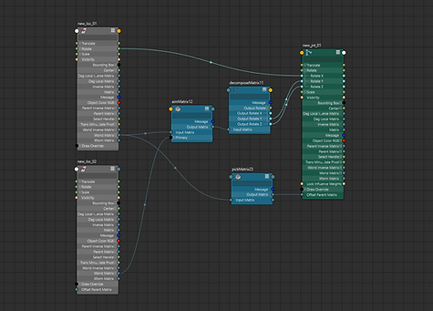
2) An aimMatrix node is used to keep the middle locator pointing towards direction of the end controllers which matters for both twist and bend. This is done by plugging loc_01's world matrix into the input matrix, giving it a starting point to aim. This makes the locator aim at loc_01, but only from a stationary point. If the other end of the ribbon is moved and the middle controller is moved up in space, it is now pointing at an area above loc_01. To fix this, loc_05's world matrix is plugged into the primary target matrix. This way loc_03 also identifies loc_05 as a point to aim at, and by also pointing at loc_05, it will point the other end towards loc_01. The loc_03 now has 2 points it is aiming at. The secondary target can then be used for a Y-up aim, but in my example I don't have that. These values are then taken and plugged into the Y & Z axis of loc_03.
The reason this issue needs to be solved is because wherever the middle points dictates how the ribbon will deform. Remember, the locator is directly driving the geometry, therefore it needs to follow the direction of the end locators. I don't want the twist to bend at an incorrect offset, I want it to bend facing the direction of the ribbon.


3) A blendMatrix node is used to drive the position and scale of the middle locator. This node is set up to be the average between loc_01 and loc_05. It is setup in the offset parent matrix so that the translation and scale values of loc_03 can be used to create a bend. The blendMatrix node is ran through a pickMatrix node where I cancelled out the rotation. I wanted to use this node for translation and scale, not rotation.

This same setup can then be replicated for the other controllers between the middle and ends to give an extra layer of control. The red controllers (loc_02 & loc_04) now follow twist, aim, bend, and scale behaviors as well.


All controllers connected to twist, bend, and scale the entire ribbon
One aspect to note is that I am using the plusMinusAverage to get rotation and not the blendMatrix. This is intentional, as those 2 nodes work differently in how they read the inputs.
The blendMatrix is reading an input entirely with orientation, position, scale, and shear. To process this input, the node uses quaternion interpolation behavior to give the most stable result. This means that it is taking the shortest possible path to reach the desired state. This works perfectly for position, however the issue presents itself with rotation. When quaternion interpolation is used, it is essentially saying "what is the shortest path within a 360° orientation". It only thinks of orienting an object, not actually rotating/ twisting it.
The plusMinusAverage node isn't reading the rotation X values as rotations or trying to interpolate orientation. It simply sees a float value, it doesn't read the input as an object orientation. This means that it'll never try to take the shortest path.
For example, say you want a controller rotated 270°:
Quaternions: 90° → 180° → -180° → -90°
In this case, -90° is a shorter path from 0° than 270°, therefore it "flips" when it hits 180° because anything past that would no longer be the shortest path.
Non-quaternions: 90° → 180° → 270°
In this case, there is no "shortest path", it is just a number that scales up.
This "flip" in the controllers can be seen in the left side ribbon below. It
severely limits animation. The right side ribbon can twist infinitely and
never flip, giving animators more freedom to push rigs.
Quaternions (red) flip at 180°, floats (green) never flip

Ribbon twist with flipping
Ribbon twist without flipping
Joint Structure Anchor
Joint Structure
This is where the main structural difference of the rigs is seen, and it is here where I recreated the "smoothness" of a NURBS shape. To recreate this, I had to achieve 2 things:
1) Positioning
2) Rotations
Both attributes follow the same idea that in a ribbon, a selected span of points will also deform the points around it. Below I have an example to show what I mean.
Joints around the animated joint are still translate and rotated
With just the single controller deforming the geometry, the areas around it move even when their controllers don't. This is the power of a NURBS ribbon, the lines are much smoother between controllers rather than a straight line from one to the next, and joints always point in the correct direction. In the below example I show a clear distinction between joints following the controllers exactly and joints following a ribbon.

Linear behavior on the left, spline behavior on the right

Node network for getting joint 3 to follow the correct position
Getting the joint positioning was the first issue I addressed. Above is an example for joint 3, directly in the middle.
1) Plugging loc_01 & loc_05 (both ends) into a blendMatrix, and plugging that into loc_03. This puts the locator at the center of the ends.
2) Then do the same process for loc_02 & loc_04 (between middle and ends), getting the middle points between loc_03 and loc_01/ loc_05.
3) Now that the locators are set, plug loc_03, loc_02, and loc_04 into a parentMatrix node. In the parentMatrix nodes, I set these weights:
loc_03: 1.000
loc_02: 0.300
loc_04: 0.300
I chose a parentMatrix over a blendMatrix here because a parentMatrix adds all influences at the same time while a blendMatrix averages influences in order. This means that with the parentMatrix I can keep both sides equal at 0.3, but with a blendMatrix one is slightly more than the other. It could technically work, but parentMatrix gives a better result more easily. The reason I chose 0.3 was because the NURBS shapes I used before were created with a surface degree of 3, and this input would mimic that surface behavior. This node also gives me the ability to change the sharpness of the bend by connecting a float to the weights value, letting me key it however I want. It's not a massive change, but it could be a useful tweak in certain cases.
Note how joint 3 doesn't follow loc_03 exactly, but rather just influenced partially by it. Changing the weight values can cause the joint to follow it 100% or 0%. I keep it at 0.3 to mimic NURBS behavior. Ribbon geometry is shown here to make visualization easier.
Getting the joint positioning was the first issue I addressed. Above is an example for joint 3, directly in the middle.
1) Plugging loc_01 & loc_05 (both ends) into a blendMatrix, and plugging that into loc_03. This puts the locator at the center of the ends.
2) Then do the same process for loc_02 & loc_04 (between middle and ends), getting the middle points between loc_03 and loc_01/ loc_05.
3) Now that the locators are set, plug loc_03, loc_02, and loc_04 into a parentMatrix node. In the parentMatrix nodes, I set these weights:
loc_03: 1.000
loc_02: 0.300
loc_04: 0.300
I chose a parentMatrix over a blendMatrix here because a parentMatrix adds all influences at the same time while a blendMatrix averages influences in order. This means that with the parentMatrix I can keep both sides equal at 0.3, but with a blendMatrix one is slightly more than the other. Now the joint is mainly driven by the controller, but it is also influenced by controllers on both sides. It could technically work, but parentMatrix gives a better result more easily. The reason I chose 0.3 was because the NURBS shapes I used before were created with a surface degree of 3, and this input would mimic that surface behavior. This node also gives me the ability to change the sharpness of the bend by connecting a float to the weights value, letting me key it however I want. It's not a massive change, but it could be a useful tweak in certain cases.

Joint rotations aim towards the locators plugged into the aim matrix
Getting the joints to point in the right direction was easy, as I had already used this same method in the controllers earlier. The X rotation, twist, is already dictated by the same controller. To get the joints to aim in the right direction, mimicking the Y-up behavior, I have the joints on both sides acting as aim targets. This way the aim always averages in between both controllers if they're moved. An important distinction about this section is that the aimMatrix can also take the joints of each side instead of the controllers. I personally think the better arc is achieved from having joints aim to the point of influence rather than the next joint in line, that feels too linear to me. The difference is small though, only noticeable at extreme deformations.
Evaluation Performance
Like I did with the hybrid ribbon, I'm going to go through the evaluation metrics for both rigs to show the differences in performance. Both ribbons have the same amount of joints, controllers, and the same exact animation playing.
Hybrid ribbon
New ribbon
With our test animation set, we can now look at 4 different visuals to see the performance difference.
1) Profiler: Visually shows the total measured time per frame to evaluate all nodes and the ribbon overall. Also shows the node costs and data categories of each node.
2) Visual Graph: Shows the dependency relationships between nodes, not animated runtime.
3) Visual Scheduling Graph: Visually shows Maya's planned node execution for animated runtime.
4) Text Scheduling Graph: Textually shows more detail in Maya's planned node execution for animated runtime.
1) Profiler
The profiler is what I will use to record the animation and look at how Maya evaluates the ribbon per frame. It will show how long it took, any nodes that create bottlenecks, how parallel the rig is, and the information of how each node was evaluated. Time is measured in microseconds (μs) and milliseconds (ms).

Hybrid ribbon animation profile, note the bottleneck at 1

New ribbon animation profile, no bottlenecks
In the examples, we are looking at how the ribbon was evaluated in 1 frame of animation. The highlighted "Main" bar (EvaluationGraphExecution) is where the total time evaluated is shown, the average time per frame for each is:
Old Ribbon: ≈ 1400 μs (1.4 ms)
Hybrid Ribbon: ≈ 1200 μs (1.2 ms)
New Ribbon: ≈ 500 μs (0.5 ms)
I can now see a dramatic increase in performance! The new rig evaluates more than twice as fast as the hybrid and nearly 3 times faster than the traditional legacy method. On the hybrid rig I can identify the 1 bottleneck forcing serialization, and upon zooming into the node, I can see it is the NURBS plane shape. In the new rig there are no bottlenecks for execution and the nodes are evaluated in a parallel friendly fashion. Joints are now no longer dependent on a NURBS shape to be evaluated, and the deformation math is all parallel.
Seeing the difference on the small scale, I can already predict that in a large scale test that the new ribbon will be significantly faster. Think back to our room with the boxes, what would be faster, telling the one person to open 90 more boxes or getting 90 more people to open the boxes?
To see how these rigs compare, I took the same ribbon animation and replicated it 100 times in the same scene.

Hybrid ribbon animation 100x profile

New ribbon 100x animation profile
Once again we are looking at a single frame of animation. From a visual standpoint, these 2 profilers are very different. The left profiler shows the NURBS shapes scattered and adding up in evaluation. The deformation math nodes are small but are still held up by the shape nodes. In the ribbon profile on the right, there are no longer any long bars cluttering the graph. Instead, all the nodes are just quick little math nodes.
In the EvaluationGraphExecution we can see a HUGE decrease in time that confirms what I predicted would happen at scale.
Old Ribbon: ≈ 8300 μs (8.3 ms)
Hybrid Ribbon: ≈ 6800 μs (6.8 ms)
New Ribbon: ≈ 2700 μs (2.7 ms)
This proves that the use of math nodes instead of deformers is spreading the workload more and getting a faster result of it. This is around a 150% increase in speed from the hybrid rig!
2) Visual Graph
Going back to the singular ribbon, the visual graph isn't going to display measured time. Instead, all it will show is the dependency relationships in the construction of the ribbon. Here, it is more clear to see what relies on what, and which nodes can be evaluated in a serialized vs parallel order.

Hybrid ribbon visual graph
New ribbon visual graph
Immediately I can tell 2 things about my new ribbon. My new ribbon isn't processing as much information (all the pointMatrixMult nodes) and there is no more bottleneck (NURBS shape). Like before though, the deformation math is spread out and parallel. Another important thing to note is that my newer rig doesn't have any cycles. My resulting ribbon graph on the right is clean, parallel, and cycle-less.
This graph also provides a useful visual aid for identifying anything being cycled or pruned.
Cycling is bad to see as it means a node or node network is depending on itself. This causes an infinite loop, therefore Maya has to resolve/ break the cycle by forcing serialization. Many legacy nodes are built with intentional cycles, causing more work needed for evaluation.
Pruning is good to see as it means parts of that node aren't needed downstream and can therefore be disregarded in evaluation. This simply means whatever is being pruned gets cut and less work is needed to evaluate that node.
In the older ribbon there are cases of both cycling and pruning. In the hybrid and new ribbons, there is no cycling at all, only pruning.
3) Visual Scheduling Graph
Returning to the animated ribbon, the visual scheduling graph is displaying how Maya anticipates the nodes to be executed in runtime.

Hybrid ribbon visual scheduling graph

New ribbon visual scheduling graph
Like the original visual graph, the same patterns can be seen here. On the left, more nodes are being processed and are being fed through the bottleneck. The right side graph shows less nodes being processed. Here I can see a "bottleneck" from loc_03, that being the middle controller that influences 2 controllers and 2 joints. I'm okay with this bottleneck though as it is purely the math connection from loc_03 to other controllers, and without this I'd have no bend.
4) Text Scheduling Graph
This is simply a text output of the scheduling graph, the same information from the visual graph will be seen here. These text outputs also show the cycling, pruning, and caching in the scheduling. The below pictures are only snippets of the full text output, but the difference between serialization and parallelism can still be seen.

Hybrid ribbon order of execution, note the blocks of many multiple nodes evaluated at the same time

Hybrid ribbon shows pruning and caching

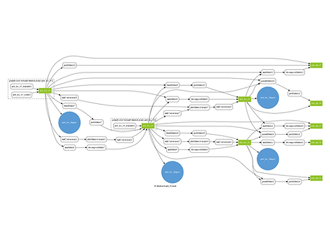
New ribbon order of execution, note how there are less nodes and nodes are more evenly spaced than in blocks
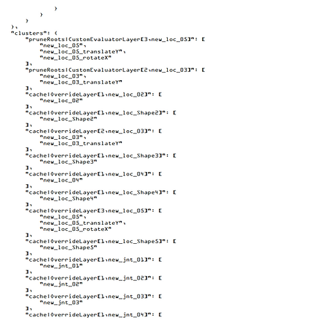
New ribbon shows pruning and caching
The text output of the visual scheduling graph makes it easier to search through nodes and see evaluation in more detail. One aspect that is easier to see in this output is the caching of nodes. Caching is good to see as it means information is being stored and doesn't need to be re-evaluated later.
In my comparison of the 2, the text version of the graph confirms what I see, that being less nodes and that the structure is more parallel.
Legacy, Hybrid, Pure
Looking between the 3 rigs, I'm happy to see the evolution of my ribbon to get to where it is now. Learning how to use the evaluation toolkit assisted me heavily with finding poor performance in my rigs as well as confirming the improvements in my newest one.


Profilers for old, hybrid, new


Evaluation graphs for old, hybrid, new
You can see the the learning process go from how to use matrix math nodes, identifying bottlenecks, and refining my rig.
The Result & Closing
My resulting ribbon created solely from math nodes proves that me new approach is significantly faster than my hybrid rig! Not only have I learned how to avoid using deformers, I learned how to remove the actual ribbon from the ribbon. All of this while also keeping the same range of motion as my prior ribbons. This experiment also showed me how helpful the evaluation tools are for finding performance blockers as well as how fast my rigs are processed in general.
While creating this ribbon though, I was wondering about how rotation values work with quaternions. I had already learned about how how all matrix math nodes produce orientations that can't go beyond 180°. My solution was to use the rotation float values, but I was wondering if it would be possible to get these same rotations from matrix outputs (like world matrix) or nodes. Upon investigation, the answer is no for vanilla Maya nodes.
This left me confused though, as plugging in a controller's world matrix directly into a joint's offset parent matrix would cause the joint to follow the controller perfectly, even when rotating beyond 180°. In every math node, the 180° angle causes the joint to flip. This is something I want to investigate further, and I can potentially see myself creating my own node in the future that solves this issue for me. For now though, I'm happy enough with the result I came up with, but this gives me something to investigate for the time being.
What I want to do next is to recreate the ribbon in Bifrost, as Maya now has the Bifrost Graph Editor that allows users to create their own modular rigging networks. It would be great to make a ribbon that I could easily customize the amount of joints and controllers, as well as automatically hooking it up to a rig.
Thank you for reading :]
If you'd like to go back and read how I created my hybrid ribbon rig, follow the link below.

Hybrid Matrix Ribbon Rig
Learn how I recreated a traditional ribbon rig in Maya using a hybrid of matrix math and NURBS.
bottom of page